

Hot Keyword:
Author:KUNYUAN Machine Manufacturer TIME:2026-08-30
A parts list becomes useful when every assembly is connected to the yarn path, loop-forming event, fabric-control task or protected support function it performs on the exact machine.
Official Groz-Beckert circular-knitting material describes large-diameter machines as using a circular array of needles, with single-jersey systems combining needles and sinkers and double-jersey systems using cylinder and dial needles. Its system-parts publication adds sinkers, selecting, intermediate and transfer jacks and emphasizes interacting functions and tolerances. Manufacturer machine selectors show that feeders, beds, controls and take-down arrangements vary by model. This walkthrough therefore explains functional layers rather than one universal construction.
Follow the production path in order: yarn storage and delivery, feeder presentation, needle-zone loop formation, fabric draw-off and take-down, then the control, lubrication, guarding and record systems that support them. At each handoff, record what enters, what the assembly controls, what evidence appears in the fabric and which model document defines service. Do not use this overview as a repair procedure. Internal access, timing, adjustment and replacement remain qualified work under the delivered manual and site isolation rules.
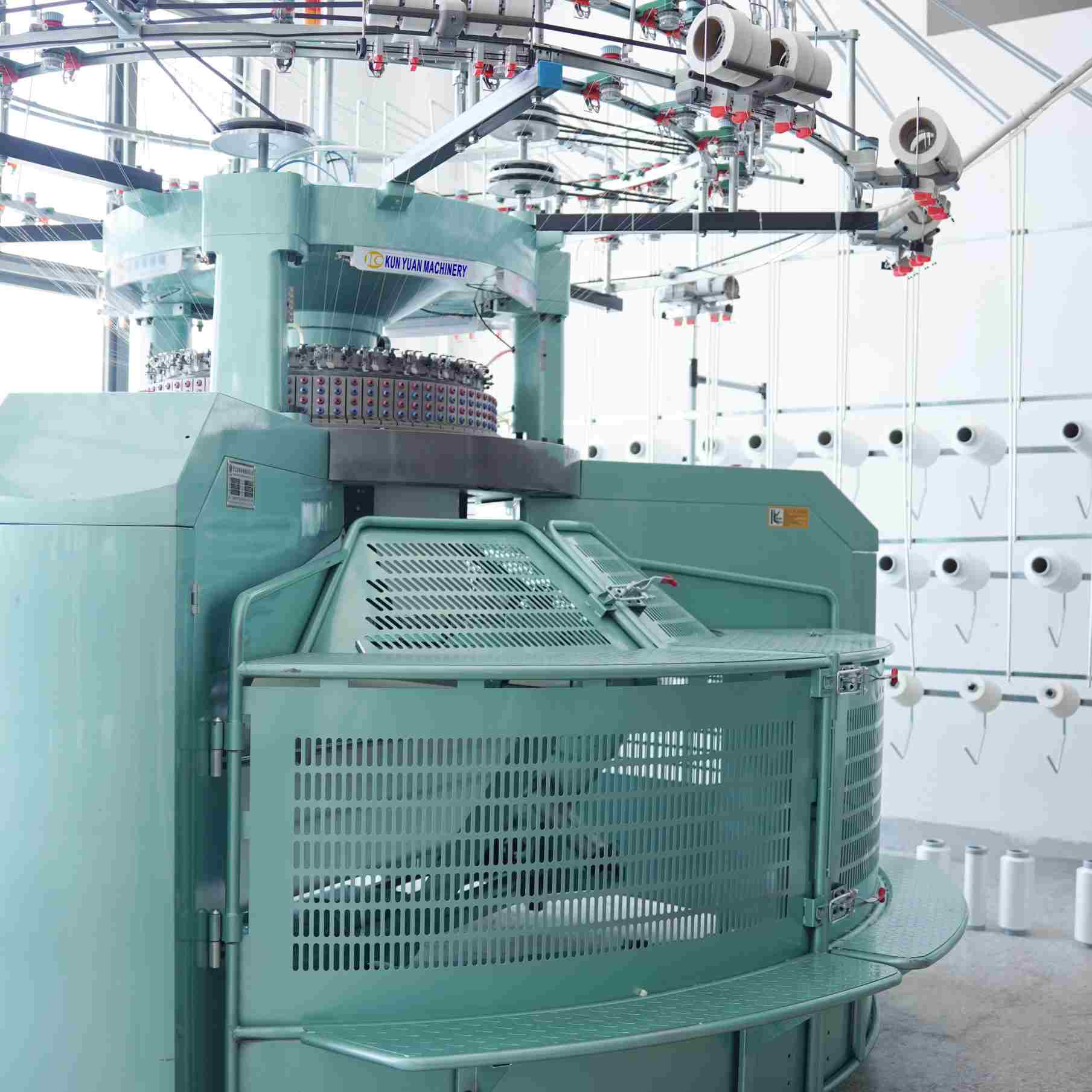
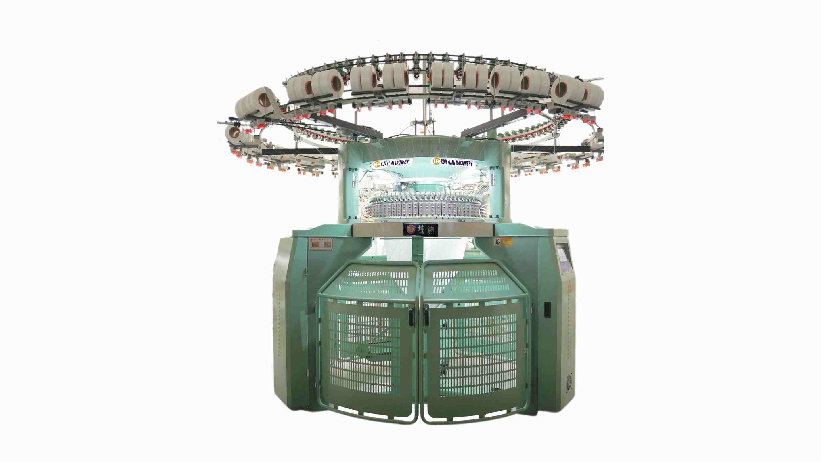
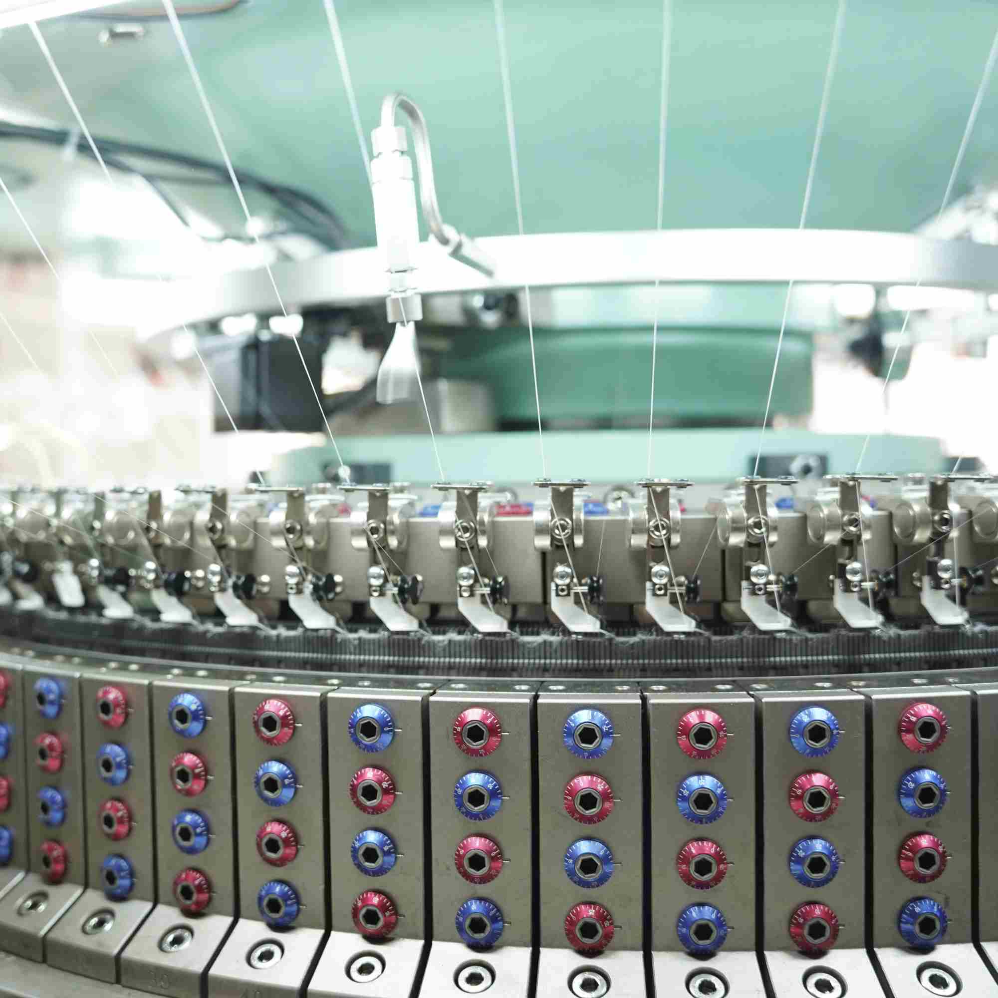
The path begins with package, lot and yarn-role control. Creel positions, guides, tension or delivery devices, stop motions and feeders present yarn to the knitting systems according to the machine build. Positive delivery, elastomer feeding, plating or striper equipment may be present on a named configuration, but none should be assumed. Draw the actual route from the supplier manual and label every package position.
The functional handoff is stable, identified yarn at the required feed point. Evidence includes package records, route inspection, alarms, event timing and the corresponding fabric coordinate. A line, missing yarn or plating error may involve this layer, yet diagnosis should preserve needle-zone and take-down hypotheses until controlled evidence narrows them. Never publish a generic tension setting for unknown yarn and hardware.
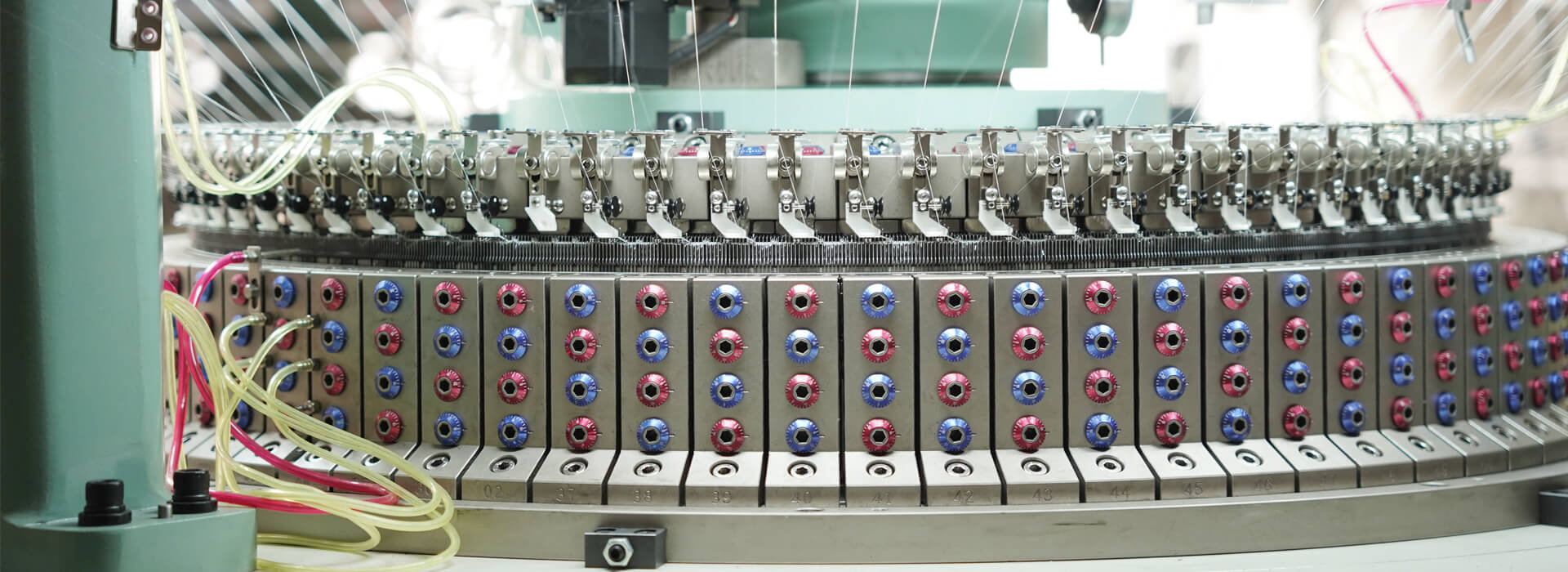
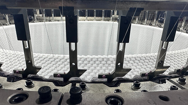
In the knitting zone, the machine's cam or selection arrangement moves compatible needles and related parts through the actions available to that build. Single-jersey configurations commonly use cylinder needles and sinkers; double-jersey machines add a dial needle system. Selecting, intermediate, coupling or transfer parts appear only where the architecture requires them. The exact sequence, timing and clearances belong to the model documentation.
Link each promised structure to the installed beds, tracks, selection and yarn feeds. Inspect fabric at marked positions for loop definition, misses, tucks, lines, holes or pattern errors. Part designations and mating systems matter because visually similar elements can behave differently. This blueprint can identify which functional group owns a question, but qualified technicians must perform internal checks and adjustments.
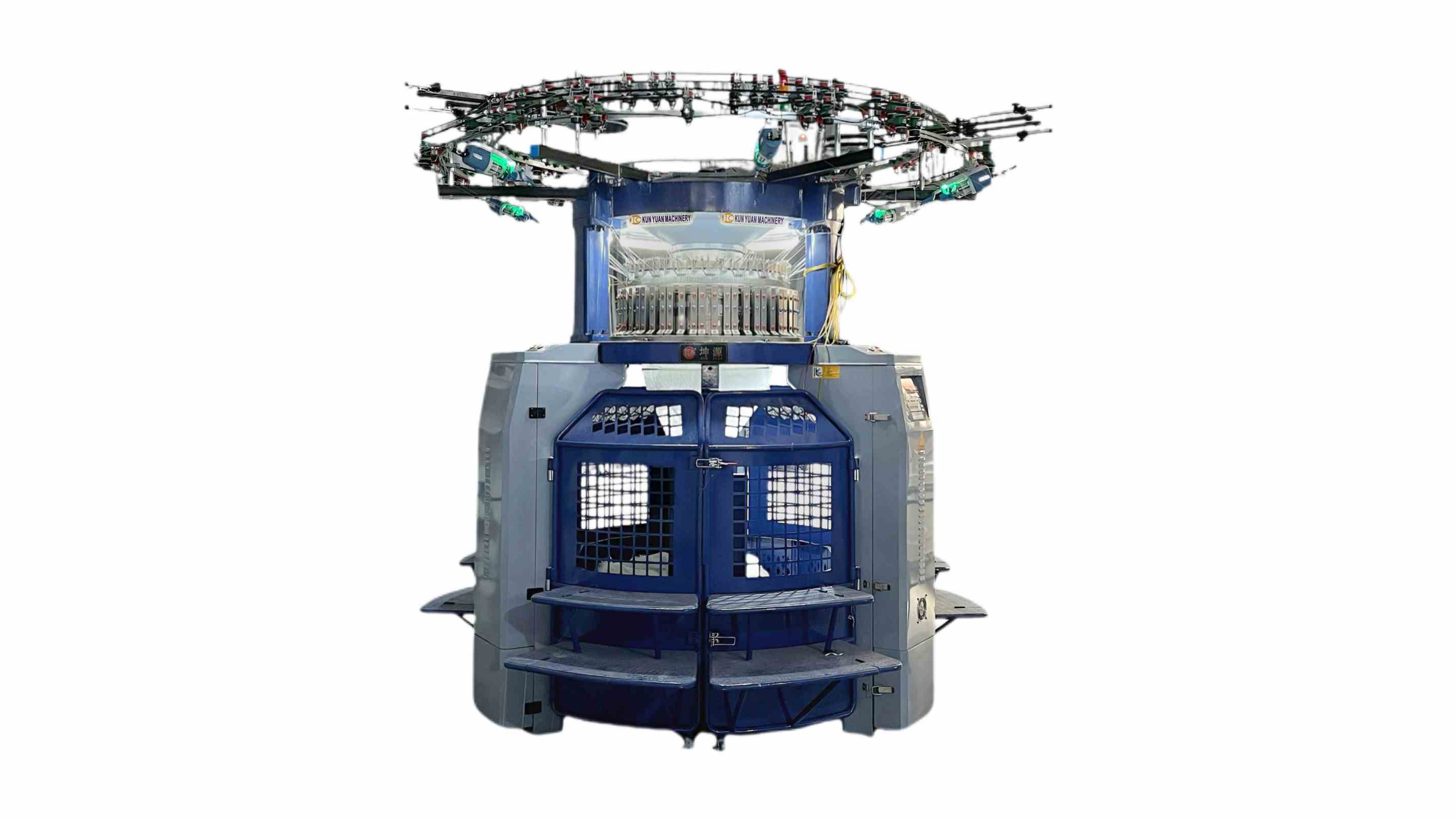
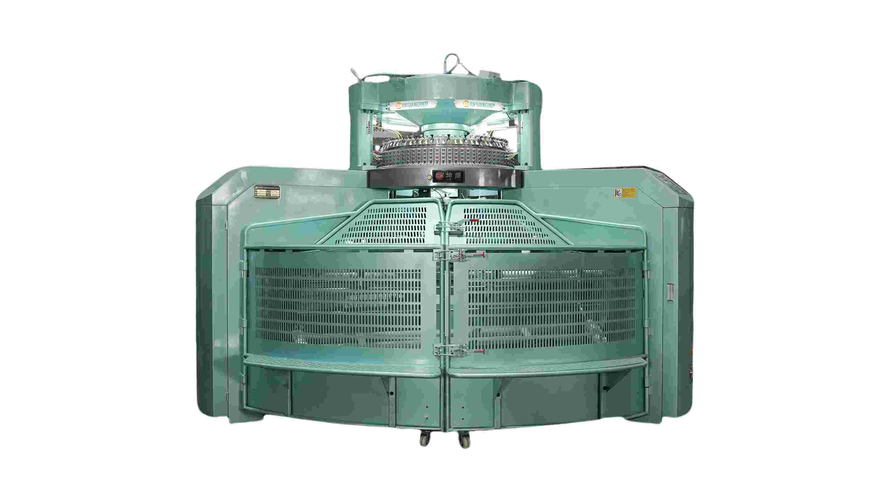
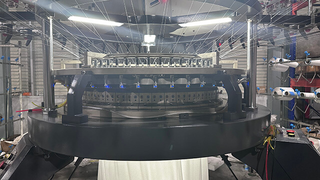
After loop formation, the fabric must be withdrawn in a controlled path. Depending on the machine, this layer may include a spreader, center tube, draw-off, take-down rollers, batching or winding, slitting or open-width equipment. Its job is not merely storage. It influences fabric tension, width presentation, roll formation and how evenly the knitting zone is loaded.
Record the actual handling route and the delivered adjustment or control references without inventing universal values. Observe fold lines, width variation, skew, roll hardness, edge damage and event marks across the full circumference or width. If a defect changes with handling, keep the knitting setup stable while the authorized take-down hypothesis is tested. The accepted output should arrive at the next process with direction and roll coordinates intact.
Drive and control systems coordinate commanded motion, status and stops; lubrication supports defined moving interfaces; guarding and interlocks protect access; manuals, backups and service records preserve recovery. The exact sensors, controller, oil system and protection design vary by machine. For each function, note what is monitored, what response occurs, which role may act and where the official instruction is stored.
Witness approved production events during acceptance, compare screen or alarm records with marked fabric, and keep required protection in service. Maintenance should identify lubrication records, critical spares, software backup ownership and escalation contacts. A complete walkthrough ends when the receiving team can trace a disturbance from yarn input through loop formation and take-down without entering a hazardous area or replacing parts by guesswork.
| Functional layer | Main handoff | Evidence in the process | Model-specific boundary |
|---|---|---|---|
| Yarn feed | Identified yarn at feed point | Package map, stop and fabric coordinate | Delivery hardware and settings |
| Loop formation | Named structure from installed systems | Repeat, faces and defect geometry | Beds, cams, selection and elements |
| Take-down | Controlled fabric to next process | Width, roll and event map | Spreader, draw-off and winding route |
| Support | Protected, recoverable operation | Logs, lubrication and backups | Controller, guarding and service roles |
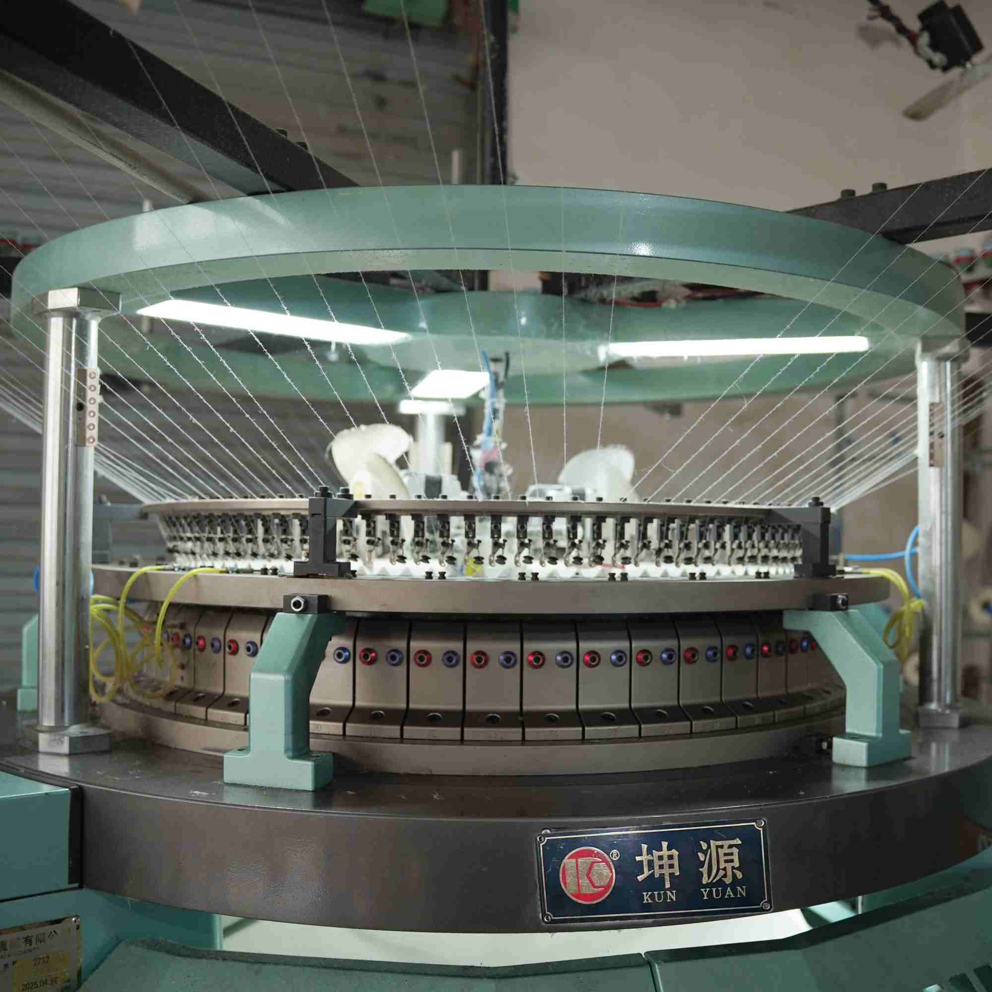
It presents the assigned yarn to a knitting system through the delivered routing and control arrangement; exact delivery hardware varies by configuration.
They can support loop formation and fabric control in many single-jersey systems, while the exact sinker design and function remain machine-specific.
A dial needle system works with the cylinder system, adding another bed and structure possibilities that require matched elements and timing.
No. Fabric withdrawal, spreading and winding can influence tension, width, fold formation and the load presented back to knitting.
No. It is an orientation map. Qualified personnel must use the exact manual, isolation procedure, tools and authorized parts for service.
The feeder-to-take-down view turns a circular knitting machine from a collection of parts into a chain of handoffs. Yarn delivery presents controlled material, the knitting zone forms the structure, take-down manages the new fabric, and support systems protect and record the process. Keeping every description model-specific makes the map useful for training and diagnosis without turning it into unsafe repair guidance.
Use the function blueprint when reviewing a Circular Knitting Machine and request the exact feeder, knitting-system, take-down and support documents for the offered build.

 Tel: +86-13859034518
 Email: info@kunyuanmachine.com
 MP/WhatsApp: +86-13859034518
 Manufacturer Address:Bacuo Village, Yonghe Town, Jinjiang City, Fujian Province