

Hot Keyword:
Author:KUNYUAN Machine Manufacturer TIME:2026-08-30
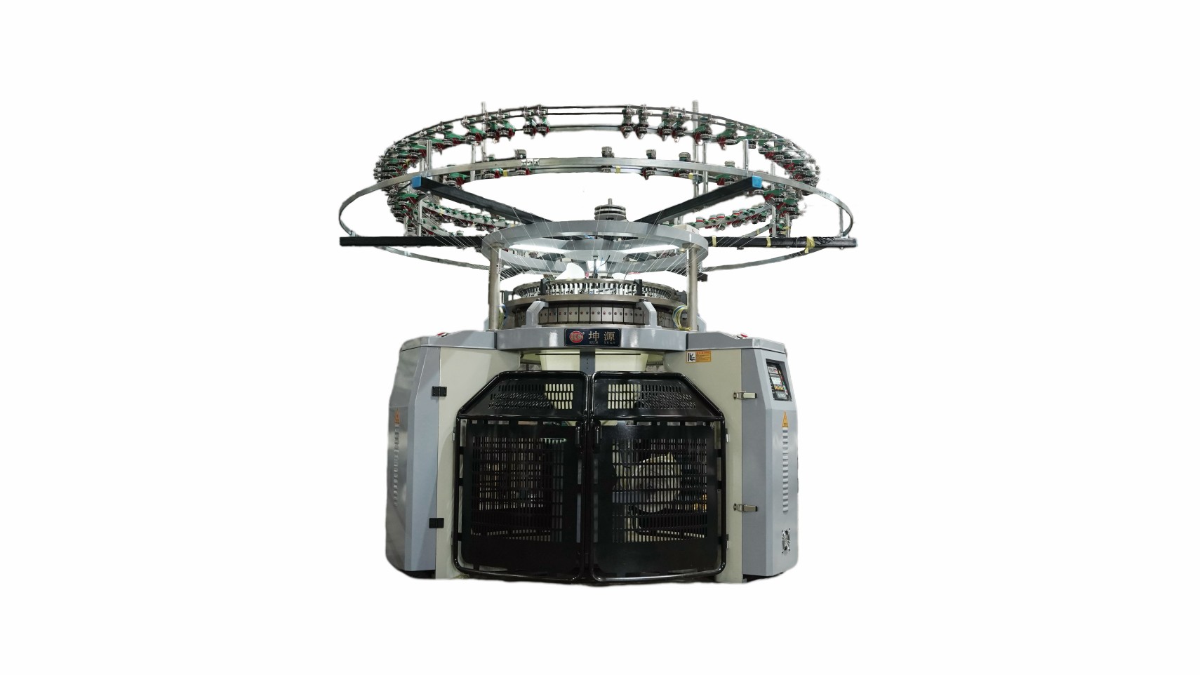
Interlock fabric is created by coordinated needle sets rather than a single setting called timing. The machine's cylinder and dial arrangement, cam paths, gauge, yarn delivery and take-down establish a physical window; any adjustment or conversion must remain inside the maker's documented procedure.
Freeze a reference fabric before discussing adjustments. Record the exact interlock structure, yarn material and count by feed, machine model, diameter, gauge, installed needles, cam arrangement, active feeds, stitch setting, yarn tension, take-down, speed and finishing route. Keep a face and reverse photograph plus a labelled sample showing one complete repeat.
Official Mayer & Cie and Groz-Beckert material illustrates that large-diameter double-jersey systems are configured around coordinated knitting elements and model-specific ranges. Published gauge or diameter lists are screening information, not permission to combine settings across models. The controlled blueprint should name the offered build and cite its machine documentation for any timing, clearance or component change.
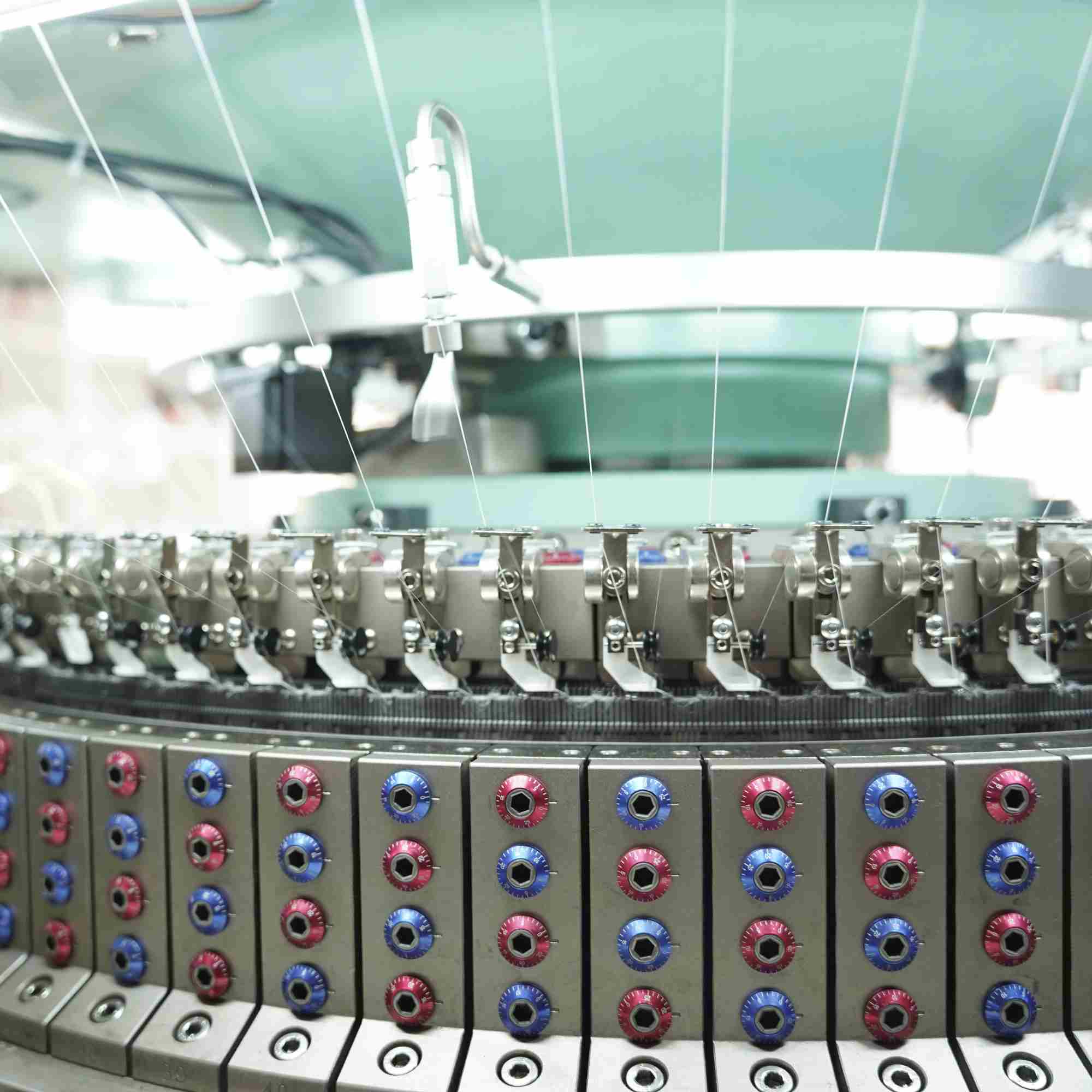
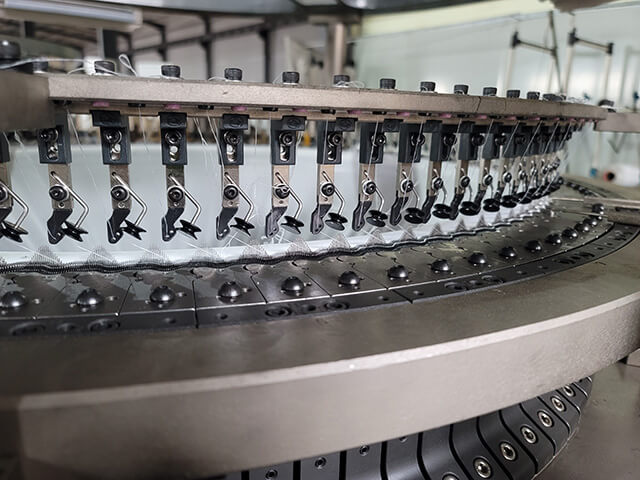
Sketch which needle set forms each visible loop and how the opposing bed contributes. Mark knit, tuck or miss actions only where the chosen cam and needle arrangement supports them. Trace yarn from feeder to clearing, feeding, knock-over and fabric withdrawal, noting the surfaces where yarn contact or poor loop control could create lines, holes or uneven density.
Use a low-complexity diagnostic fabric before a commercial pattern. Its purpose is to make bed interaction and repeating positions visible around the tube. A repeating defect at a machine-related interval should be mapped to physical feeders, tracks and needle groups; a random yarn fault belongs in a different branch of the investigation.
Timing language can refer to relative needle movement, cam position or another model-specific reference. Record the machine maker's named datum, measurement method, permitted range, tool and authorization level. Photograph or measure the baseline under the approved safe procedure before loosening a component. Never borrow a numerical setting from another machine or online example.
Change one controlled variable at a time and mark the corresponding roll position. Observe loop formation at authorized low-speed conditions, then return to a stable production test. If needle contact, abnormal sound, heat, repeated breakage or a new defect appears, stop and restore the documented baseline rather than compensating through unrelated yarn or take-down changes.
Gauge narrows the candidate machine and needle system, but yarn diameter, fibre, twist, friction, elastomer use and structure determine whether the loop can be formed consistently. List all yarns by role and include the difficult lot in the trial. Confirm exact cylinder needles, dial needles and mating elements rather than treating a gauge label as a complete spare-parts description.
Establish a controlled yarn-delivery and stitch-setting range on the reference structure. Inspect both faces for barring, holes, dropped loops, needle lines, spirality and uneven density. Carry a marked sample through relaxation or finishing before judging dimensional stability; a greige tube can conceal changes that become clear only after the fabric is processed.
For a planned move among interlock, rib or another supported double-knit structure, list cam changes, needle set-out, yarn reassignment, feeder setup, take-down values, cleaning, safety checks and inspection steps. Identify conversion parts and confirm that the exact machine model permits the target route. A marketing statement about flexibility does not establish a safe field conversion.
After installation, rotate and inspect under the authorized procedure, then knit a diagnostic section before the saleable article. Record elapsed changeover work, start-up waste, stop causes and the first accepted finished sample. Close by proving restoration to the original structure as well; reversible flexibility matters when the mill must return to an existing order.
| Blueprint layer | Controlled reference | Fabric observation | Stop condition |
|---|---|---|---|
| Loop architecture | Cylinder/dial action and yarn path | Face, reverse and repeating position | Intended action is unclear |
| Timing | Maker datum and measured baseline | Marked response to one change | Contact, heat or new defect |
| Gauge system | Needles, mating parts and yarn roles | Loop clarity and finished dimensions | Unverified substitute |
| Changeover | Parts, settings and restoration sequence | First accepted target and return samples | No recoverable baseline |
No. The datum and adjustment method are model-specific. Use the machine maker's documentation and qualified service boundary.
No. Yarn diameter and behaviour, structure, loop length, needle system and finishing requirements must be trialled together.
The two-bed construction can show different evidence on each face, including needle lines, missed loops, yarn faults and registration issues.
Some configured machines support relevant conversions, but required cams, needle set-out, parts and procedures must be confirmed for the exact model.
A controlled setup record, diagnostic knit, accepted finished target fabric and demonstrated restoration of the previous approved structure.
Interlock technology is manageable when its blueprint keeps loop architecture, the maker's timing datum, gauge-specific knitting elements and changeover evidence together. That record protects the machine from improvised adjustments and lets the mill distinguish true structural flexibility from a conversion that has not been engineered or proven.
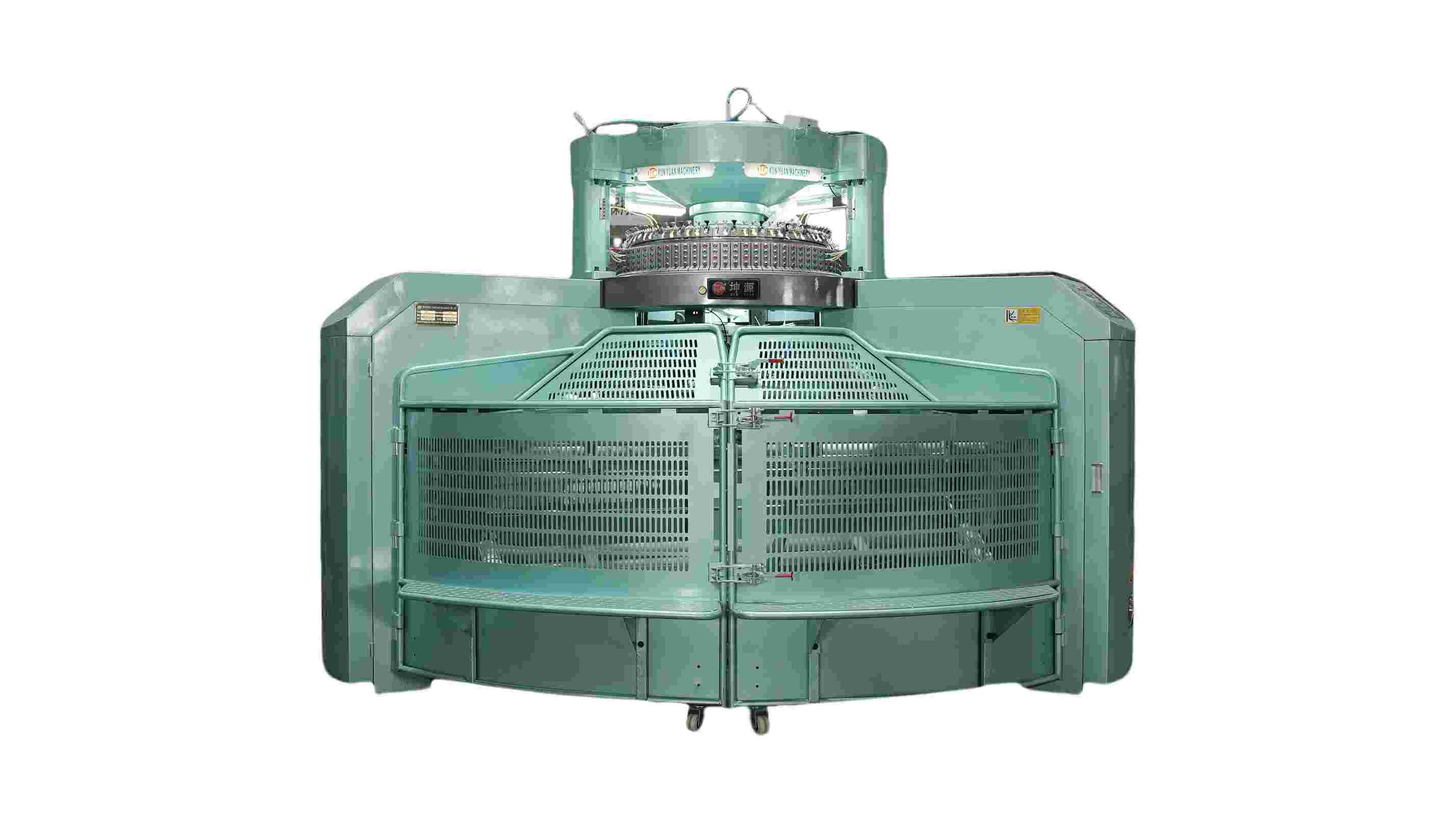
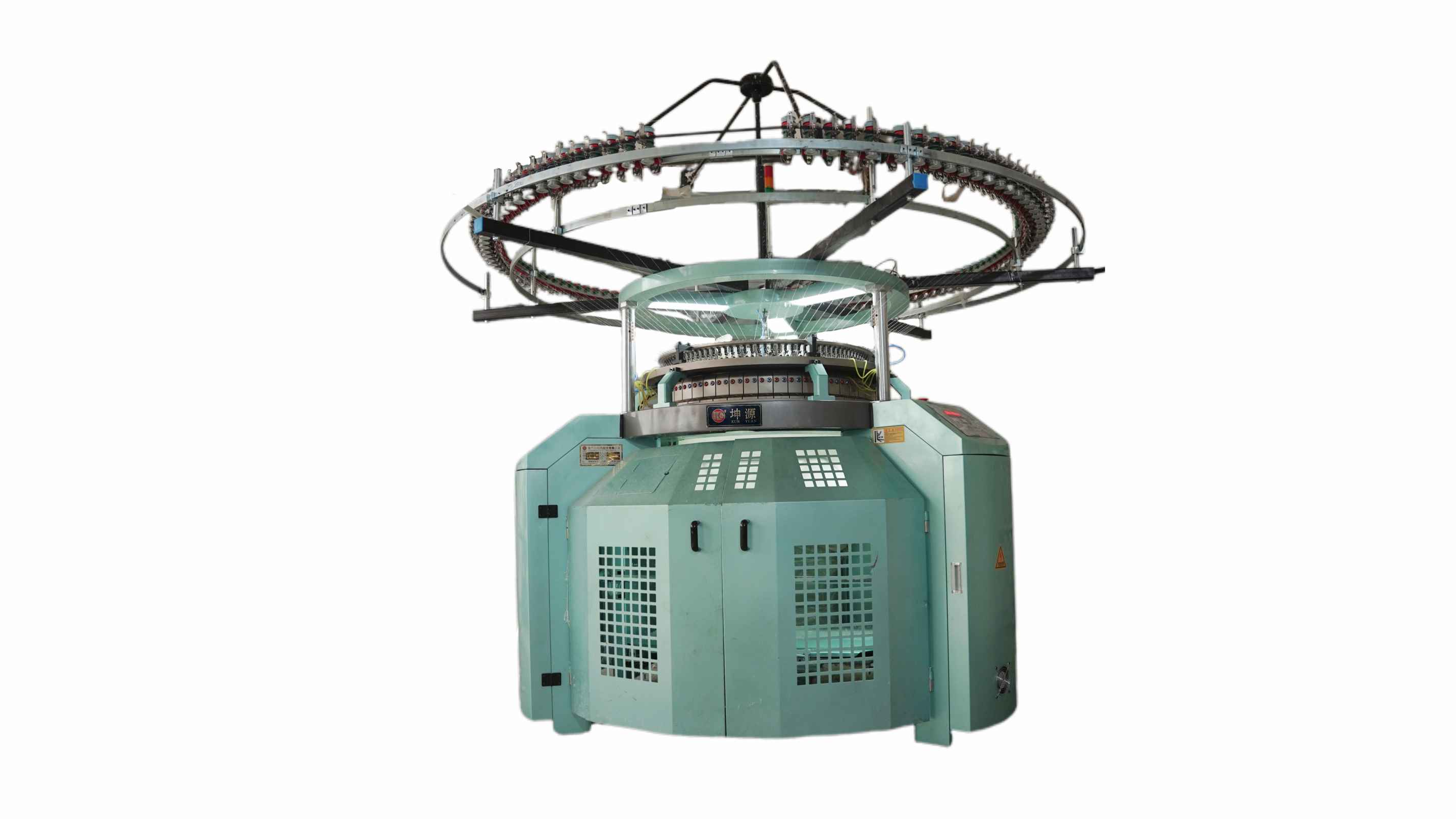
Use the four-sheet blueprint while evaluating the interlock circular knitting machine range and require model-specific timing references, complete knitting-element identity and reversible changeover proof.

 Tel: +86-13859034518
 Email: info@kunyuanmachine.com
 MP/WhatsApp: +86-13859034518
 Manufacturer Address:Bacuo Village, Yonghe Town, Jinjiang City, Fujian Province