Interlock quality depends on coordinated needle beds, not on the name of either bed alone
An interlock circular machine uses cylinder and dial knitting elements in a defined relationship. Their timing, cam paths, yarn presentation and withdrawal must be assessed as one installed system through fabric evidence.
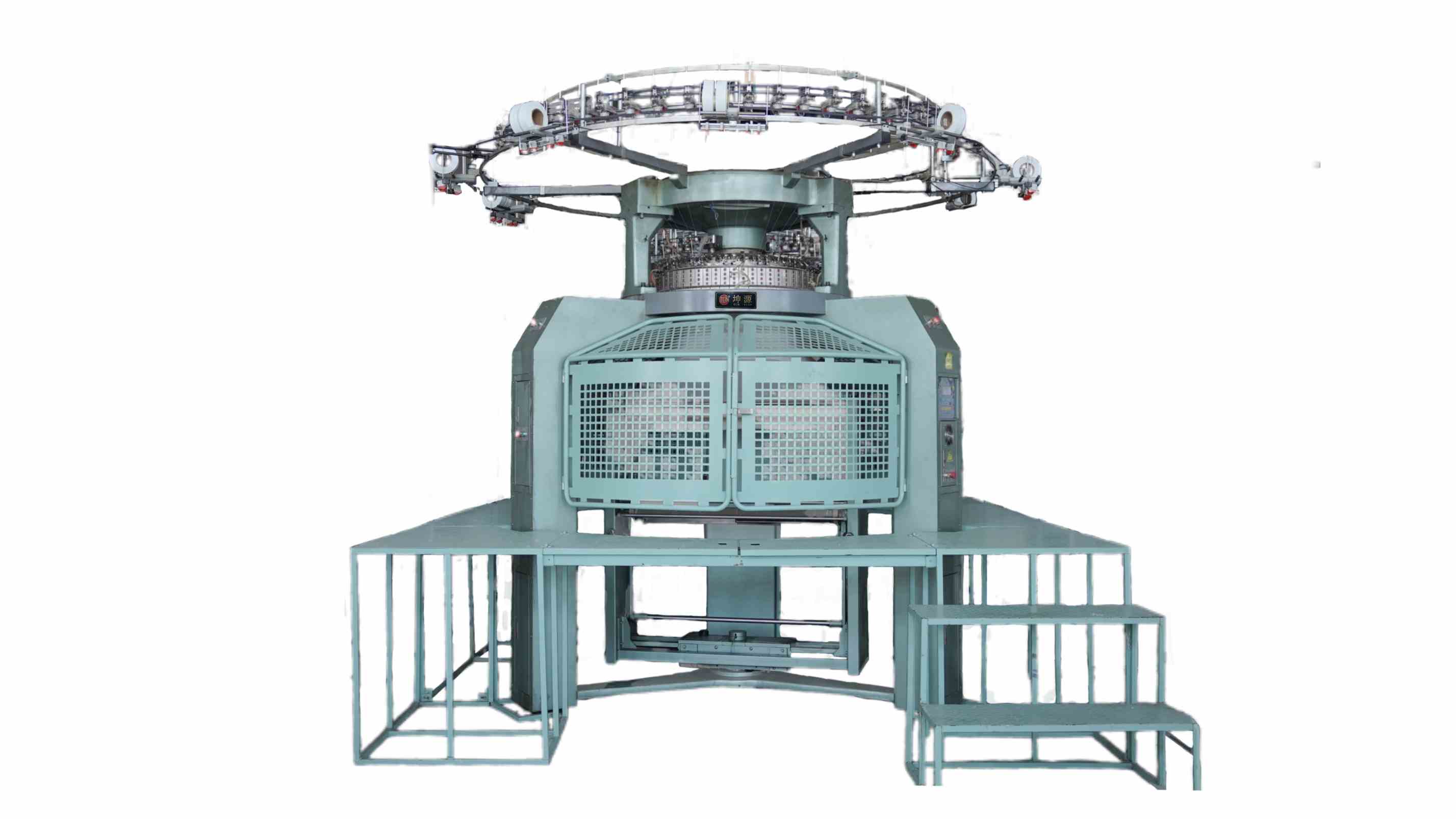
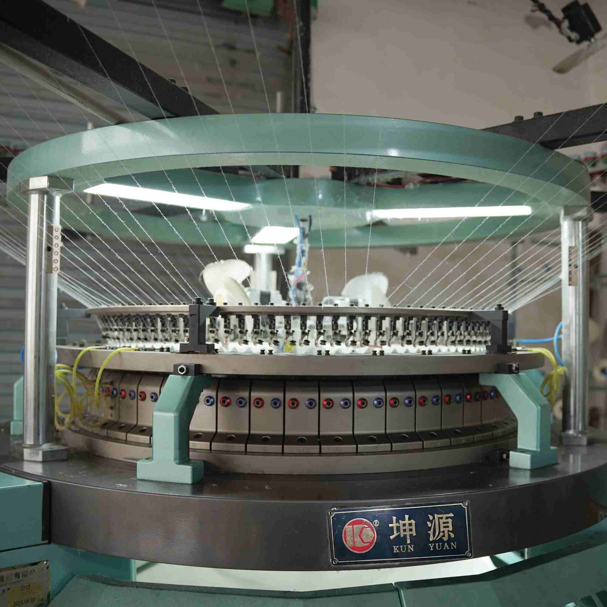
Start with the intended interlock construction and the exact offered machine. Draw the cylinder and dial beds, identify the relevant tracks or selection arrangement and show where yarn is presented. Record gauge, needle and sinker system identities, cam or dial settings only from controlled manufacturer documents, and the take-down condition used for the trial. This is a test notebook, not a generic timing recipe.
Official interlock portfolios from Terrot and the broader circular-machine references from Mayer and Cie and Groz-Beckert show that double-knit systems are configuration-specific. Their pages help identify the components and questions, but they do not authorize copying a timing value or combining options across models. Keep guards, manual rotation, adjustment and service work within the exact machine procedure and qualified roles.
01
Document cylinder and dial element relationships before any trial
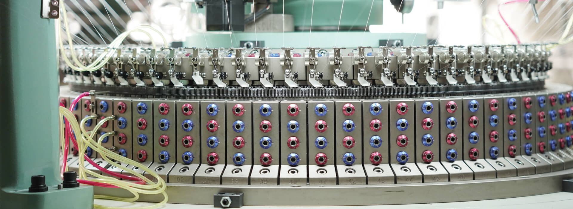
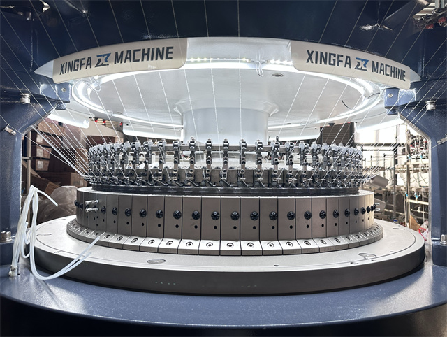
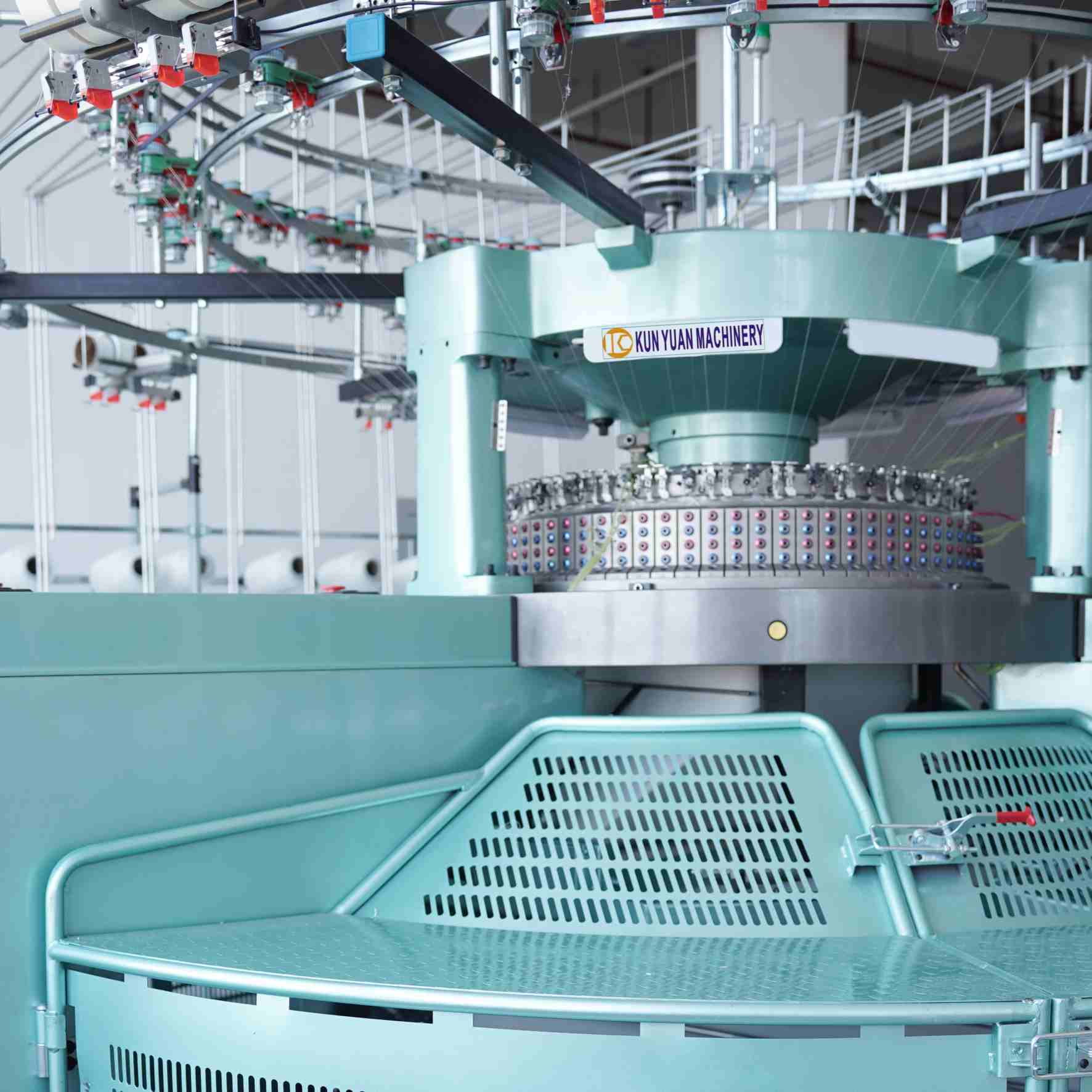
Photograph and record the machine identification, then map the cylinder needles, dial needles and associated knitting elements by the manufacturer's terminology. Note track or cam positions relevant to the chosen structure, yarn entry points and any change parts installed. Do not infer compatibility from appearance: needle, sinker, cam and dial components must match the exact machine, gauge and approved part specification.
Create a simple loop-sequence sketch from the model documentation and compare it with the fabric target. Mark which bed action is expected at each observation point without publishing adjustment values. If the configuration in the quotation differs from the build record, stop the technical review. A timing experiment is meaningless when the team has not established which elements and arrangements are present.
02
Use safe, model-specific observation to check the needle-bed sequence
Follow the manufacturer's procedure for stopped-state inspection, controlled observation and any permitted manual movement. Guards, interlocks and hazardous energy controls must remain effective. A blog cannot define safe hand positions, dial clearance or universal timing angles. The qualified technician should compare the installed references with the model's controlled documentation and record deviations without improvising at production speed.
Use an appropriate setup yarn and observe whether cylinder and dial actions present and receive yarn as intended for the structure. Note contact marks, abnormal sound, damaged latches or hooks, missed loops and inconsistent clearing only from safe observation points. Preserve the original condition before adjustment. If several variables change together, a later clean fabric cannot show whether timing, yarn delivery or a replacement element resolved the problem.
03
Translate bed coordination into both-face fabric evidence
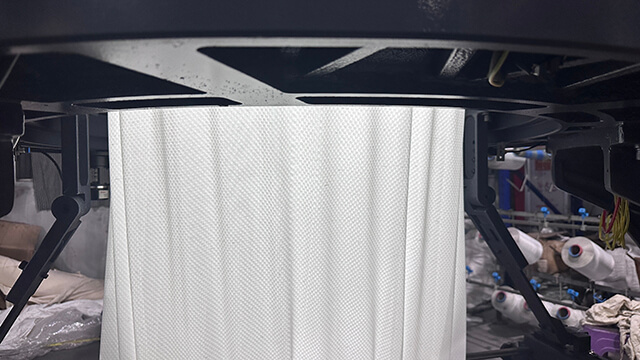
Inspect the technical face and reverse under consistent light. Record holes, vertical lines, press-offs, uneven columns, dial-related marks, barring and dimensional imbalance without assigning a cause before checking geometry. A fixed circumferential interval may connect a fault to a feed or element position; a course interval may connect it to an operating event. Mark those relationships on the tube before cutting samples.
Include warm-up, a stable production interval, a planned stop and restart. Compare fabric width, weight basis, stitch appearance and recovery after the agreed relaxation or finishing step. A correct-looking short greige sample can hide instability that appears after more courses or downstream handling. Keep the exact machine record and fabric marks together so the technician can distinguish bed coordination from yarn or take-down effects.
Freeze a repeatable interlock setup and replacement boundary
Once the trial passes, freeze the exact model configuration, controlled setting references, yarn lots, delivery arrangement, take-down state and inspection result. List the approved needle and related element identities and define how replacements are issued by position and lot. An operator should not compensate for suspected bed-timing or component problems by drifting unrelated yarn or withdrawal settings outside the accepted window.
Repeat the article after a normal cleaning, element replacement or product change using the documented procedure. Compare the second fabric with the retained sample and record any correction needed before release. The handover should identify the operator checks, the conditions that stop production and the work reserved for qualified service. This turns cylinder-dial timing from an undocumented technician skill into a controlled quality record.
Identify the delivered two-bed configuration before interpreting timing.
Interlock cylinder-dial test record
Test layer
Record
Fabric or machine evidence
Hold condition
Build identity
Beds, gauge, tracks and elements
Matches offered model
Part or configuration mismatch
Timing observation
Procedure and reference positions
No contact or missed action
Uncontrolled deviation
Fabric response
Tube marks and both-face inspection
Balanced repeat after restart
Repeating or growing defect
Release window
Setup revision and replacement list
Receiving-team repeat
Result cannot be reproduced
Keep observation and adjustment inside the model-specific safe procedure.Use fabric geometry to separate bed, yarn and withdrawal evidence.
Interlock timing questions
Can one cylinder-dial timing value be used on every interlock machine?
No. Timing and clearances are model- and configuration-specific and must come from controlled manufacturer procedures.
Why inspect both sides of interlock fabric?
The two-bed structure can show imbalance, missed actions or recurring marks differently on the face and reverse.
Does a vertical line prove a dial-timing fault?
No. Preserve its geometry and compare yarn delivery, element condition, feed position, bed coordination and take-down before naming the cause.
When should production be held?
Hold when the build differs from the record, elements may contact, damage is visible, or the approved structure cannot be reproduced safely.
What belongs in the handover file?
Keep the model and build map, controlled setting revision, element identities, marked fabric, replacement history and repeat-run result.
Conclusion
Interlock technology is controlled through the relationship between two needle beds. A build map establishes what is installed, model-specific observation checks the sequence, fabric geometry reveals the response, and a repeat run proves the accepted window. This approach protects quality without turning a general article into an unsupported timing instruction.
Use this timing notebook while reviewing the industrial circular knitting machine range and require the exact cylinder-dial build, controlled procedure and marked interlock sample to remain in one technical file.





 Tel: +86-13859034518
 Email: info@kunyuanmachine.com
 MP/WhatsApp: +86-13859034518
 Manufacturer Address:Bacuo Village, Yonghe Town, Jinjiang City, Fujian Province