Hot Keyword:
YOUR POSITION:HOME > Blog >

Circular Pile Knitting Machine Technology: Loop Control and Finishing

Author:KUNYUAN Machine Manufacturer TIME:2026-08-30

MENU
Pile-fabric architecture sheet

The saleable surface starts with a stable knitted foundation and ends after a named finishing route

Pile appearance cannot be released from one machine-side photograph because the ground, pile yarn, loop retention, take-down and later cutting, raising or shearing steps contribute different evidence.

Draw the fabric in layers before discussing settings. Identify the technical face, ground construction, pile-yarn role, any tie or retaining action, intended loop state and the surface expected after processing. Add yarn material and lot, greige and finished measurement basis, usable width, visible defect standard and the exact finishing sequence. This architecture sheet prevents terms such as plush, fleece, terry, loop pile and cut pile from being treated as interchangeable.

Kunyuan presents circular pile machine families separately from pile-fabric finishing equipment, including a dedicated raising and shearing product category. That distinction is operationally important. A knitting trial can show loop formation and retention in greige fabric, while a downstream trial reveals surface cover, loose fibre, streaks, hand and dimensional movement after treatment. The offered machine, installed parts and finished buyer-yarn sample define the supported route; broad product-page language should remain a screening reference.

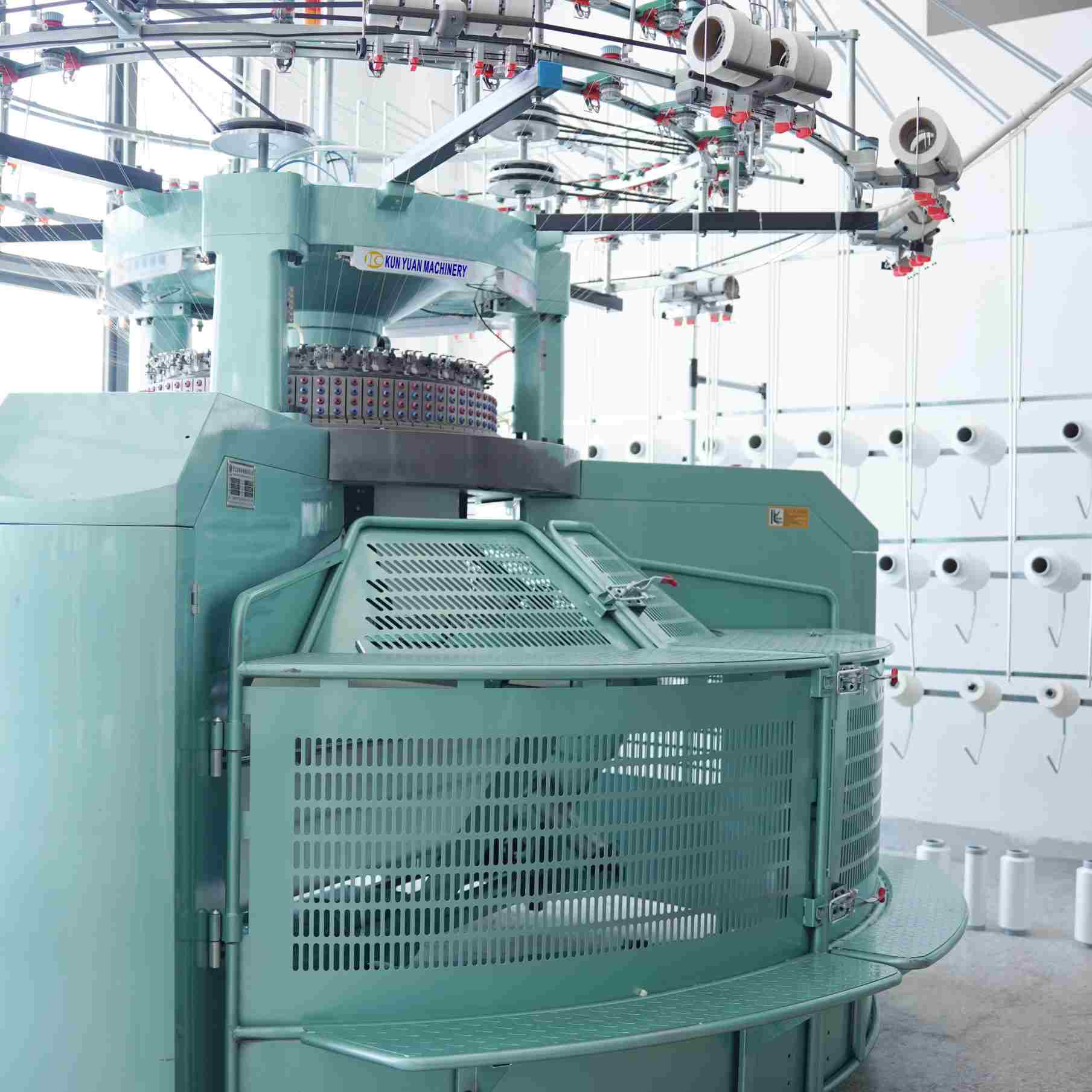
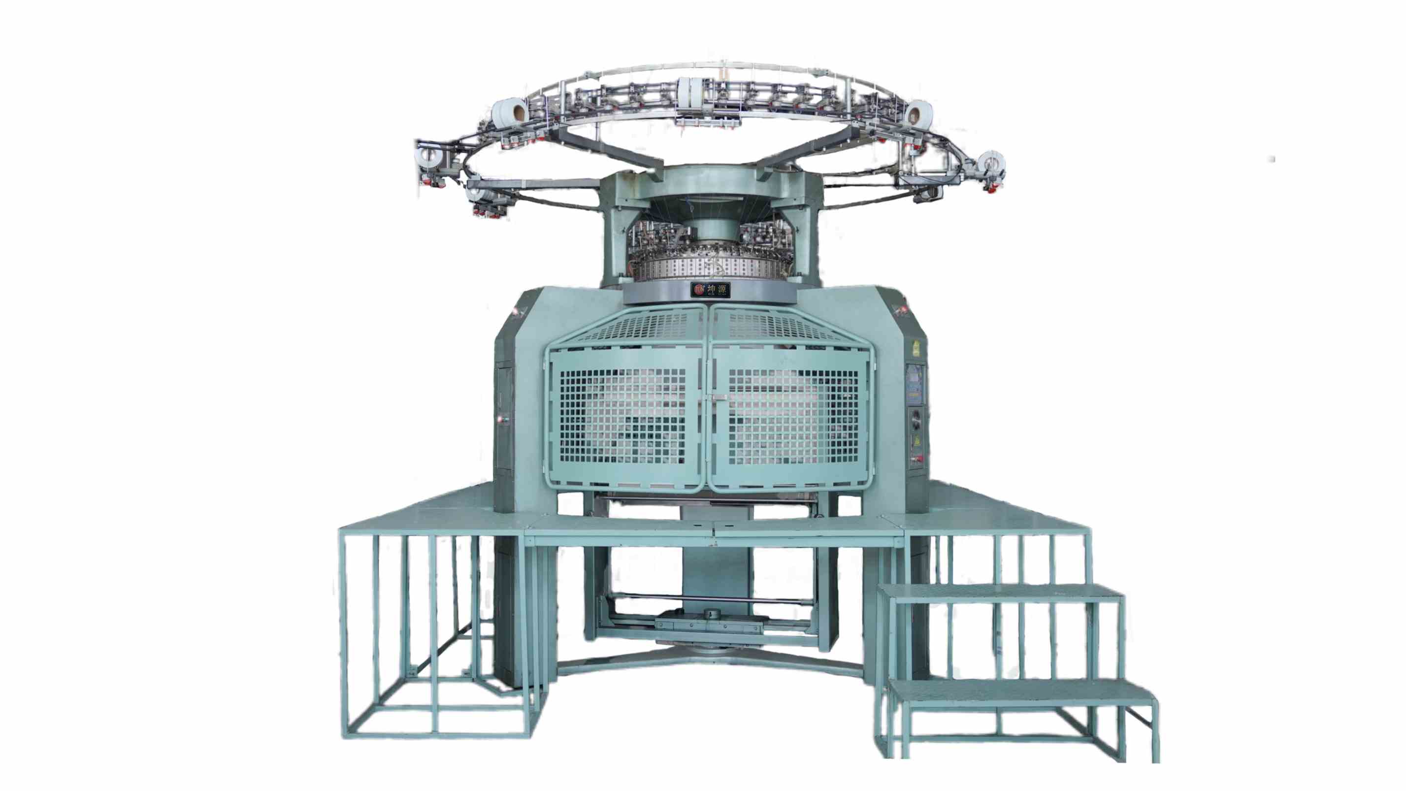
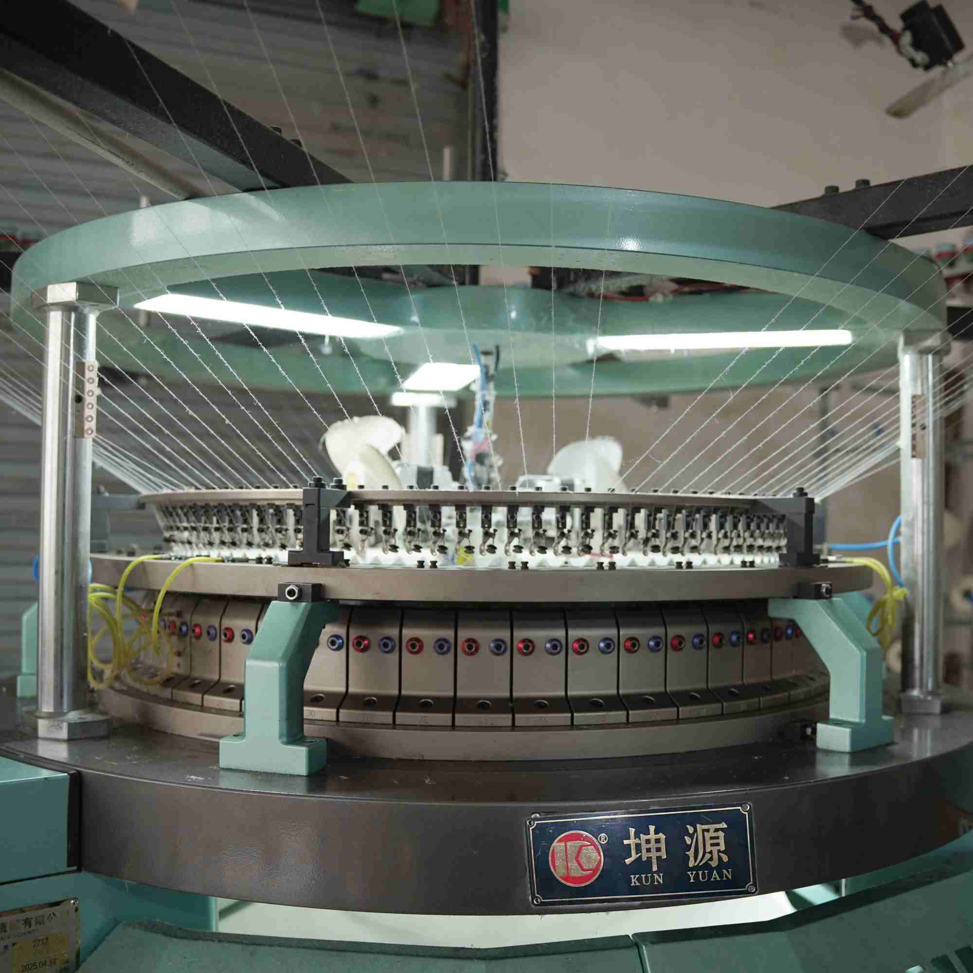
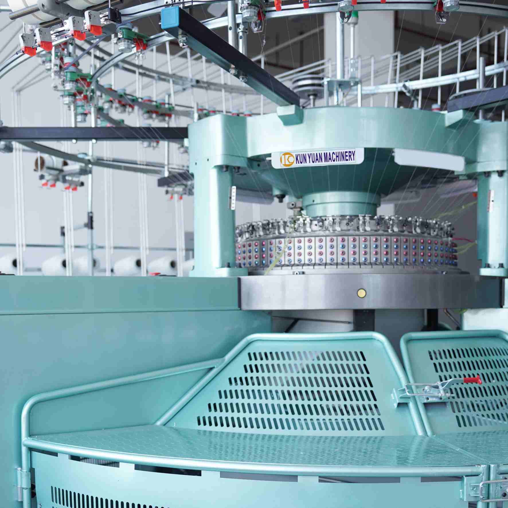
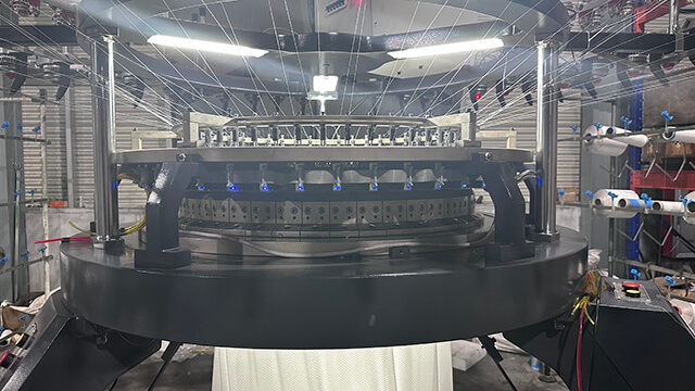
Circular pile knitting machine and loop-architecture reference
Read the ground and pile-yarn roles as separate architecture layers.

Stabilize the ground structure before judging pile height

The ground carries the pile yarn and transmits take-down force, so it needs its own specification. Record the ground yarn, knitting arrangement, visible stitch relationship and any binding role separately from the effect yarn. Inspect both faces under consistent light and mark machine direction. A surface that appears full can still conceal weak anchoring, ground lines or local distortion on the reverse.

Compare greige and finished measurements from the same labelled piece. Width, weight, length response and surface development may move together, and improving only one value can destabilize another. When a ground defect repeats at a fixed interval, preserve the roll position and machine reference before changing settings. The diagnosis should start from repeat geometry, not from a general assumption that every surface line is caused by pile-yarn tension.
Give the pile yarn a separate path, role and observation record

Identify the pile yarn by material, count, lot and package build, then trace its route from package to loop-forming point. Record the installed delivery and monitoring devices without inventing universal tension values. The correct operating window is machine-, yarn- and structure-specific and belongs in the supplier procedure or approved trial record. Keep the ground and pile settings on separate lines so one adjustment is not mistakenly copied to both roles.

Include a production package change and a controlled restart. Mark any loose loop, bare patch, band, fly accumulation or unexpected yarn event on the roll. If the surface becomes uneven, compare package condition, delivery route, loop formation and take-down before assigning a cause. A detector state can narrow the search, but physical yarn and fabric evidence remains necessary for a defensible correction.

Test whether the formed loops survive handling before surface development

Observe the looped surface at the machine, after winding and after representative transport or handling. Note pulled loops, uneven loop length, exposed ground and recurring bands. Do not infer a cut-pile result solely from uncut greige loops. If the commercial route cuts or otherwise develops the surface, preserve an unprocessed control strip beside the processed sample so the origin of a later defect can be traced.

Use the target product's most difficult yarn or surface density in the boundary trial. The purpose is not to publish a general capability figure; it is to confirm that the quoted build can form and retain the required architecture under a recorded condition. Any change to yarn, gauge, pile mechanism or fabric handling that affects retention should reopen the relevant sample approval.

Release the surface only after the specified cutting, raising or shearing route

Label a full-width piece before it enters finishing and record its orientation and roll position. The finisher should document the route used for the approved result. Inspect the processed surface for uniform cover, lines, bare areas, loose fibre and contamination, then recheck width, weight and dimensional response. A finishing change can alter the appearance enough to hide or amplify a knitting variation.

When comparing trials, change one documented factor at a time where practical. Keep finishing-machine work under its own operating and safety instructions; a circular knitting article is not an adjustment manual for raising, cutting or shearing equipment. Close acceptance only when the knitting team and finisher can connect the saleable surface to the same traceable greige sample and machine setup.

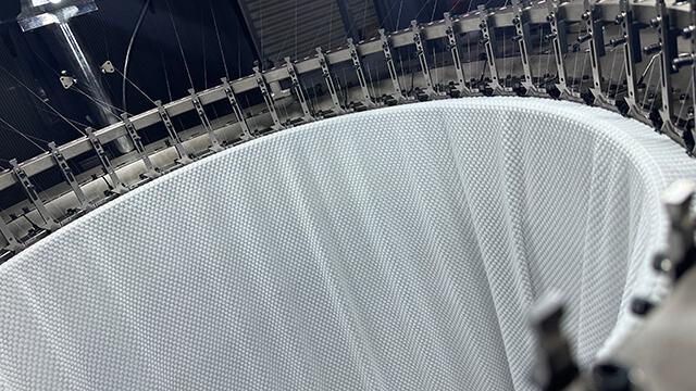
Greige pile fabric used to inspect ground and loop retention
Preserve a marked greige strip before downstream surface processing.

Pile architecture and evidence matrix

Layer or stageControlled inputObserved evidenceRelease boundary
Ground structureGround yarn and stitch relationshipBoth faces and dimensional baselineFoundation remains stable
Pile formationPile yarn path and loop actionLoop distribution and event mapDelivery and formation are repeatable
RetentionHandling and withdrawal conditionPulled loops, bands and exposed groundGreige survives transfer
Surface finishingNamed process and sample identityCover, hand, dimensions and defectsCommercial finish is accepted

Application release boundary

Keep three claims separate in the technical file: what the circular knitting machine forms in greige fabric, what a named downstream finishing machine changes, and what the finished product test confirms. Classify every requested result as demonstrated on the offered build, dependent on a stated option or finishing route, awaiting a boundary trial, or outside the current offer.

Finished pile surface compared with its marked greige control
Release commercial appearance only after the specified finishing route.

Circular pile architecture questions

Is every pile surface formed completely on the knitting machine?

No. The knitting stage creates a defined greige architecture, while cutting, raising, shearing or other finishing may create the commercial surface.

Can pile height be set from a universal online value?

No. Use the exact machine documentation and a controlled yarn-and-structure trial for the offered configuration.

Why retain an unprocessed strip?

It allows a later surface defect to be compared with the original ground, pile formation and roll position.

Does a fuller greige loop always mean a better finished fabric?

Not necessarily. Loop security, ground stability and the actual finishing route must all meet the written product brief.

What closes pile-fabric acceptance?

A traceable finished sample should pass surface, dimensional and defect checks while remaining linked to its greige evidence and machine setup.

Conclusion

Circular pile technology becomes auditable when the ground, pile path, loop retention and surface finishing are treated as separate but connected layers. Paired greige and finished evidence shows what the knitting machine actually formed and what downstream equipment changed, avoiding unsupported claims about a complete surface from one production stage.

Apply this architecture sheet when reviewing the pile fabric circular knitting machine range and ask the supplier to identify the greige construction, named finishing route and finished acceptance sample for each promised pile product.

Need Help?
Please leave your contact information to get our latest catalog
Get In Touch Now >
Kunyuan Machinery Manufacturer

Tel: +86-13859034518

Email: info@kunyuanmachine.com

MP/WhatsApp: +86-13859034518

Manufacturer Address:Bacuo Village, Yonghe Town, Jinjiang City, Fujian Province

NEW KEYWORD

About Us

Products

Information